Why Wheel Loader Load Capacity Is Different at Different Reach Heights
A wheel loader’s load capacity is rarely a single fixed number, even though many operators treat it that way. The truth is that what a loader can safely lift changes as the bucket rises, tilts, and reaches farther from the machine. A load that feels perfectly stable at ground level can push the machine toward instability once it’s raised to full height. Understanding why this happens protects your operators, your equipment, and the work around you. This post breaks down five reasons load capacity shifts with reach height, covering how load center moves as you lift, how tipping load defines stability, how hydraulic force changes at different heights, how bucket position affects the load, and how operating conditions influence real-world capacity. With this knowledge, you can plan lifts more safely and get dependable performance from your loader across every working height.
Load Center Changes With Lift Height
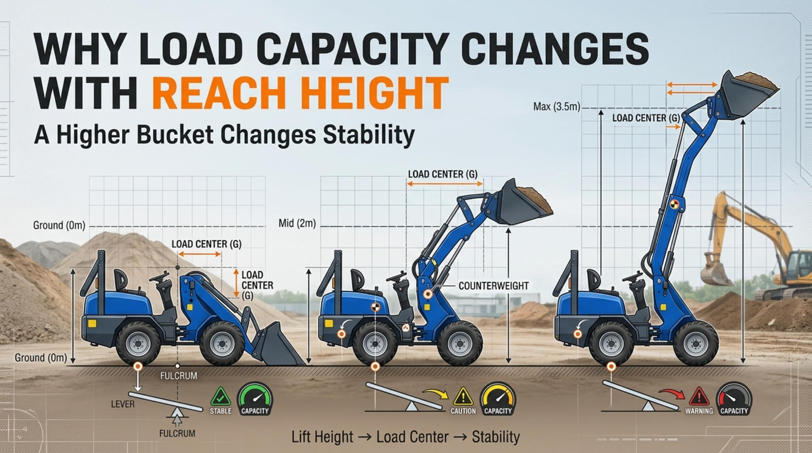
The load center is the distance between the load and a reference point on the machine, and it plays a decisive role in stability. When a wheel loader carries a load low and close to the frame, that load sits near the front axle, which acts as the machine’s balance point. In this position, the loader stays stable and can handle heavier weights with confidence. The moment you begin raising the bucket, though, the geometry starts to work against you, and the load’s position relative to the front axle begins to shift.
As the boom lifts, the load moves both upward and, depending on the linkage design, often farther forward. This increases the load center, meaning the weight is now acting through a longer lever arm against the front axle. A longer lever multiplies the tipping effect of the same weight, so a load that poses no problem near the ground exerts far more leverage when raised. The higher and farther out the load travels, the more the machine’s stability margin shrinks.
This is why safe lifting capacity drops as lift height increases. The loader hasn’t lost any structural strength; the physics of leverage simply reduce how much weight it can carry without risking a forward tip. Operators who understand this relationship know to check rated capacity at the specific height they plan to work, rather than assuming ground-level figures apply everywhere. Respecting the changing load center keeps the machine planted and predictable, and it prevents the dangerous surprise of a load that feels secure until it’s lifted into a position where the leverage finally overwhelms the machine’s balance.
Tipping Load Limits Stability
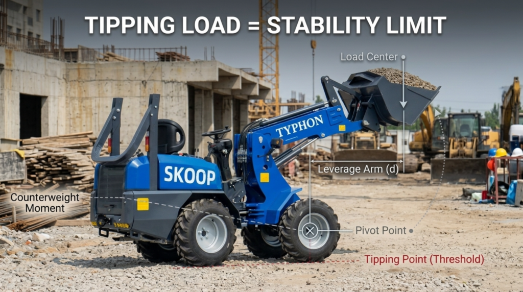
Wheel loaders are frequently rated by tipping load, a figure that describes the amount of weight at which the machine reaches the edge of stability and its rear wheels begin to lift off the ground. It represents a critical boundary, because once a loader passes that point, it can pitch forward and lose control of the load. Manufacturers publish tipping load ratings so operators have a clear reference for how much the machine can handle before stability becomes a genuine concern.
Safe operating capacity is always set well below the tipping load, using a safety factor that provides a buffer between normal work and the point of instability. This margin exists precisely because real jobsites introduce variables that can erode stability without warning. Understanding tipping load helps operators recognize that the rated safe capacity already accounts for a cushion, and that pushing beyond it eats into the protection that keeps the machine grounded.
Higher lift positions make it far easier to approach the tipping load limit, and the reason ties directly back to leverage. Several factors combine to raise this risk as the bucket climbs:
- Increased load center, which lengthens the lever arm acting against the front axle.
- Raised center of gravity, which reduces the machine’s resistance to tipping forward.
- Reduced stability margin, which shrinks the buffer between working load and the tipping point.
Because of these combined effects, a load that stays comfortably within the tipping limit at ground level may edge dangerously close to it once raised to full height. This is exactly why operators should never assume a single capacity figure applies across all lift positions. Checking the rated capacity for the specific height and reach of each lift keeps the machine safely within its stable range and prevents the machine from creeping toward the tipping threshold during routine work.
Hydraulic Lift Capacity Changes
Beyond the question of stability lies a second limit: the hydraulic system must actually generate enough force to raise and hold a load at any given height. Lifting capacity isn’t only about whether the machine stays balanced; it’s also about whether the cylinders can produce the force required to move the load through its full range of motion. These two limits work together, and the lower of the two governs what the loader can safely accomplish at a particular height.
Cylinder geometry has a major influence on how much lifting force is available at different points in the lift cycle. As the boom raises and the angles between the cylinders and the linkage change, the mechanical advantage of the hydraulic system shifts. At some positions, the geometry allows the cylinders to apply force efficiently, while at others the same hydraulic pressure produces less usable lifting force. This means the machine’s effective lift capability can vary throughout the arc of the lift, not just at the top or bottom.
Hydraulic pressure and system design round out the picture. The pressure the system can generate, combined with cylinder size and linkage design, determines the maximum force available to raise and hold a load. If the load demands more force than the geometry and pressure can supply at a given height, the loader simply can’t lift it safely, regardless of how stable the machine might otherwise be. This is why two loaders with similar stability ratings can differ in what they lift at height, since their hydraulic systems and linkages convert pressure into force differently. Operators benefit from knowing that hydraulic capability is not constant across the lift, and that reaching maximum height may reduce the force available for the final portion of a demanding lift.
Bucket Position Affects the Load
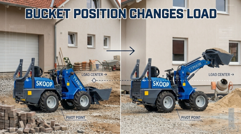
The way the bucket is angled and positioned changes the effective distance between the load and the loader’s pivot points, and that distance is central to how much the machine can safely carry. A load held tucked back against the machine sits closer to the pivot points and the front axle, keeping the lever arm short and the capacity high. Roll or extend that same load forward, and the distance grows, increasing the leverage the load exerts and reducing the effective capacity.
Bucket angle matters more than many operators realize. When a bucket is curled back, its contents stay close to the machine and the load center remains modest. When the bucket is dumped forward or the material shifts toward the front lip, the load’s center of mass moves outward, lengthening the lever arm against the pivot points. The same weight now demands more of the machine’s stability and hydraulic force simply because of where it sits relative to the loader.
A few practical points help operators manage this relationship:
- Keep loads tucked back during travel and lifting to minimize the load center.
- Avoid carrying material forward in the bucket when working at height, since it reduces effective capacity.
- Account for attachment geometry, because different attachments position the load at different distances from the pivot points.
Attachment position adds another layer, since specialized attachments often carry their load farther forward than a standard bucket. A pallet fork, for example, holds its load out ahead of the machine, which naturally increases the load center compared to material held snug in a bucket. Understanding how bucket angle and attachment position shift the load helps operators keep the effective capacity as high as possible and avoid the reduced margins that come with carrying weight farther forward than necessary.
Operating Conditions Matter
Rated capacity figures assume relatively ideal conditions, but real jobsites rarely match the test environment. Ground slope, surface quality, attachment weight, and the type of load all influence the actual safe capacity at any given moment, and each can reduce what the machine can handle compared to its published numbers. Treating the maximum rated capacity as a constant across every height and every condition is a mistake that invites instability.
Ground conditions have an immediate effect on stability. Working on a slope shifts the machine’s center of gravity and changes how the load acts against the tipping point, and lifting on an incline can dramatically reduce safe capacity compared to level ground. Uneven or soft surfaces introduce the same risk, because a tire settling into soft ground or a wheel dropping into a rut can tilt the machine and push a routine load toward instability without warning.
The load itself and the attachment also change the equation. Consider how these factors affect real-world capacity:
- Attachment weight, which counts against the machine’s lifting capability and reduces what’s left for the load.
- Load type, since shifting, uneven, or unstable materials behave differently than a solid, settled load.
- Load stability, as loose material can move during lifting and suddenly alter the load center.
Because these variables stack on top of the height-related effects already discussed, safe capacity should always be evaluated for the specific situation rather than assumed from a single figure. A loader working on level ground with a settled load at moderate height operates very differently from the same machine lifting an uneven load on a slope at full reach. Operators who account for ground, surface, attachment, and load conditions, alongside lift height, make safer decisions and get consistent, dependable performance from their equipment across the full range of work.
Conclusion
Wheel loader load capacity changes with reach height because several factors work together as the bucket rises. The load center lengthens the lever arm against the front axle, the tipping load limit becomes easier to approach, hydraulic force varies with cylinder geometry and pressure, bucket and attachment position shift the load farther forward, and jobsite conditions add their own influence. No single capacity number captures all of this, which is why the maximum rating should never be assumed constant at every working height. By checking rated capacity for the specific height, reach, and conditions of each lift, you protect your operators and equipment while getting reliable performance from the machine. Review your loader’s load charts, match every lift to the conditions in front of you, and operate with the confidence that comes from understanding how capacity truly behaves.
Frequently Asked Questions
1. Why does a wheel loader’s load capacity drop as the bucket is raised?
Capacity drops because raising the bucket increases the load center, the distance between the load and the front axle that serves as the machine’s balance point. As the load moves upward and often forward, it acts through a longer lever arm, which multiplies its tipping effect against the axle. The same weight that stayed stable near the ground now exerts far more leverage at height. The machine hasn’t lost strength; the physics of leverage simply reduce how much it can safely carry. This is why you should always check rated capacity at the specific height you plan to work.
2. What is tipping load, and how is it different from safe operating capacity?
Tipping load is the weight at which a wheel loader reaches the edge of stability and its rear wheels begin to lift off the ground. It marks the boundary where the machine can pitch forward and lose control. Safe operating capacity is set well below the tipping load using a safety factor, creating a buffer between normal work and instability. That margin exists to absorb the real-world variables of a jobsite. Because higher lifts make the tipping point easier to approach, staying within the rated safe capacity, not the tipping load, keeps the machine grounded.
3. How does the hydraulic system affect what a loader can lift at height?
The hydraulic system must generate enough force to raise and hold a load, and that available force changes throughout the lift. As the boom rises, cylinder geometry shifts the mechanical advantage, so the same hydraulic pressure produces different amounts of usable lifting force at different positions. If a load demands more force than the geometry and pressure can supply at a given height, the loader can’t lift it safely, even if the machine stays balanced. Both hydraulic capability and stability set limits, and the lower of the two governs what the machine can do at that height.
4. Why does bucket angle or attachment position change load capacity?
Bucket angle and attachment position change the distance between the load and the loader’s pivot points. A load tucked back against the machine keeps that distance short and capacity high. When the bucket is dumped forward or material shifts toward the front lip, the load’s center of mass moves outward, lengthening the lever arm and reducing effective capacity. Attachments like pallet forks naturally hold their load farther forward than a bucket, which increases the load center. Keeping loads tucked back and accounting for attachment geometry helps preserve as much safe capacity as possible.
5. Should I treat the maximum rated capacity as the same at every height?
No. Maximum rated capacity is not constant across every height or condition. Load center, tipping limits, hydraulic force, and bucket position all change as the bucket rises, and jobsite factors add further influence. Ground slope, uneven or soft surfaces, attachment weight, and load type can all reduce actual safe capacity below the published figure. A loader lifting a settled load at moderate height on level ground behaves very differently from the same machine at full reach on a slope. Always evaluate capacity for the specific height, reach, and conditions of each individual lift.